Forensics: Genesis 2 with original Mega Amp
Darren Wershler and Ace
This is a brief but particularly interesting teardown because the console in question — a Sega Genesis model 2 VA3 — contains one of Ace and Villahed’s original and influential Mega Amp boards, produced in 2014.
The Sega Genesis model 2 VA3, which has what Ace refers to as a “3/4 motherboard” in his Sega Genesis model guide, is immediately identifiable from the underside because its mainboard only extends partially across the width of the case. This is noticeable when looking through the console’s bottom vents — there is a visible gap after the RF shielding ends. In the guide, Ace notes that “These are generally superior to full motherboard Genesis Model 2s out of the box, though they’re harder to find.”
In our particular console, the upper RF shielding has been removed and discarded, because the height of the original Mega Amp board prevented it from fitting under the shielding.
Mainboard
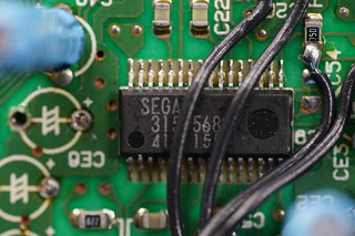 The main difference between the mainboard in this console and earlier revisions (excluding VA2 and VA2.3 ) is that the pair of quad op-amps in the audio amplifier on VA0, VA1 and VA1.8 boards is gone. In its place is a Sega 315-5684 chip, manufactured by ROHM. This is a custom all-in-one audio amplifier, which also includes the power-on reset circuit.
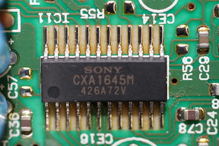 The 315-5684 chip features a second-order low-pass filter with external capacitors to adjust the cutoff frequency, and a mixer with an adjustable low-pass filter, again using external capacitors. The 315-5684 also integrates a stereo headphone driver with adjustable gain and low-pass filtering through external resistors and capacitors. On the Genesis model 2 revisions that use this configuration (VA2, VA2.3, VA3, VA4), it delivers audio from the internal preamp to the expansion connector for passthrough to the Sega CD model 2. The video encoder is also different; there can be up to 4 different chips in use (Ace has confirmed 3 of them). This particular console has a Sony CXA1645.
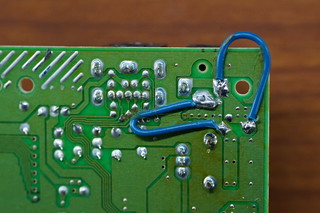 On the underside of the mainboard, Sega has installed two blue bodge wires. Not all boards in this revision have these wires, so it’s difficult to say exactly why they are there. We speculate that Sega’s engineers may have judged the traces on the mainboard to be too thin and may have added these additional wires to increase the amount of copper for the current to pass through.
The Mega Amp
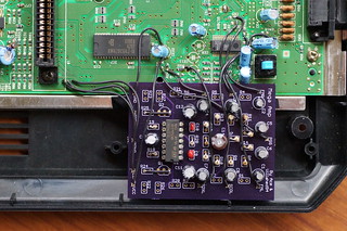 The Mega Amp board itself was clearly fabricated at OSH Park; their signature purple soldermask makes it immediately identifiable. There are three of these original Mega Amp boards in existence, two in Ace’s personal collection, and happily, the third is now in the Depot’s permanent holdings.
The Mega Amp in this console follows an unfiltered setup. This means that the cutoff frequency for the low-pass filter is 21.16 kHz, achieved by using 160 Kohm resistors and 47 pF capacitors on the amplifier (due to the extreme amount of inaudible high-frequency sound produced by the YM2612 and YM3438, a low-pass filter is necessary to prevent distortion).
The intention behind the Mega Amp’s unfiltered circuit design is to cover the average range of human hearing, from 20 Hz to 20 kHz. This approach provides significantly clearer sound overall; a board with the Mega Amp’s filtered circuit design has a cutoff frequency of 3.68 kHz, which is low within the audible spectrum, so it’s very noticeable. On the other hand, 21.16 kHz is outside the typical range of human hearing.
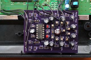 There are some visible bodge wires on the Mega Amp itself. It was originally designed with a transistor buffer on the stereo outputs in order to drive headphones for a Sega Genesis model 1 VA7. However, this didn’t work all that well, and produced audible clipping. It is also redundant for every other version of the Genesis, so instead, the wires bypass these buffers from the bases of the transistors to the left and right outputs from the circuit.
Because of the messiness of this circuit, when the Mega Amp was revised to version 2.0 in 2017, the transistors and TL074 were replaced with a single TDA1308 headphone driver paired with a TL072. The intent of this decision was to simplify the design by having the TDA1308 supply stereo audio directly, and to use the TL072 for mono mixing.
However, the Pro version of the Mega Amp 2.0 replaces the TL072 with a TL074. Part of this chip functions as a preamp, which passes audio through the expansion connector via transistors for passthrough to the Sega CD model 2. The TDA1308 follows the preamp to deliver stereo audio out the DIN connector or the headphone out on a Genesis model 1 VA7, while the rest of the TL074 handles mono mixing to the DIN connector. This setup allows for varying low-pass filter levels, depending on whether the audio output comes from the preamp on the TL074 or the final output on the TDA1308. In most cases, the expansion connector delivers unfiltered audio while the headphone out and DIN connector on the console are filtered. In terms of the final sound, this design has slightly clearer frequencies on unfiltered sound and slightly more noticeable filtering on filtered sound.
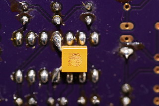 On the underside of the Mega Amp, there is an additional 0.1 uF ceramic capacitor that isn’t visible from the top of the board. It’s bodged between 5V and ground, and it functions as a bypass capacitor to filter noise on the 5V input to the TL074. It’s there simply because there was no room in the upper footprint of the board for it, reflecting the preliminary state of this design. There also appears to be no power filtering on the Mega Amp for 5V.
Remarks
The basic circuitry in the Mega Amp continues to inspire, appearing with various modifications and improvements in designs by Helder, Zeruel (who has produced both regular and pro versions, and db electronics, with still more versions in development by The Real Phoenix and Sterling Farrance. This proliferation is somewhat remarkable, given the relative lack of variation in amp designs for other consoles. By first collecting these various designs in one location, we hope to eventually arrive at some sort of conclusion about their relative performance, but this also raises the problem of measurement, as the modding community has no audio equivalent for Artemio’s 240p Test Suite, and measuring devices like oscilloscopes, which are expensive and complex, are accessible to only a handful of people involved in the community. As a result, our next question involves how to establish some sort of baseline for comparison.